

How To Upload Arduino Code Into A Microchip
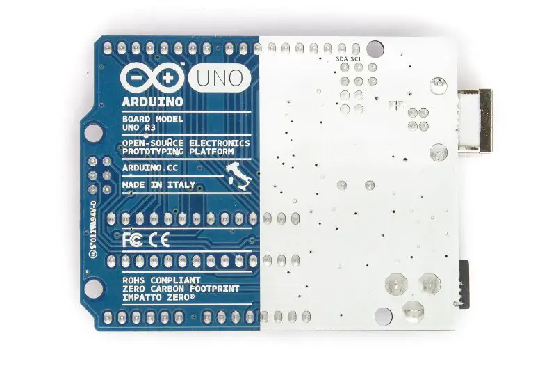
The Arduino Uno is an open-source microcontroller board that is based on the Microchip ATmega328P (for Arduino UNO R3) or Microchip ATmega4809 (for Arduino UNO WIFI R2) micro-controller by Atmel and was the kickoff USB powered board developed by Arduino.
Both Atmega328 and ATmega4809 accept a built-in bootloader, which makes it very convenient to flash the board with our lawmaking. Like all Arduino boards, we can programme the software running on the lath using a language derived from C and C++. The easiest evolution environment is the Arduino IDE.

- What is the full form of UNO in Arduino UNO?
- What are the Specs of Arduino UNO?
- Is Arduino a Microcontroller or Microprocessor?
- How many programs can Arduino UNO run?
- Arduino UNO Board Layout
- Arduino UNO Pinout /Pivot diagram(Updated):
- Schematic of Arduino UNO Rev3(latest):
- Dimensions of Arduino UNO:
- Datasheet of Arduino UNO Rev3
Arduino UNO R3 consists of six analog inputs , fourteen digital input/output pins (of which 6 can be used every bit PWM outputs), a sixteen MHz ceramic crystal resonator , a USB-B port , an ICSP header , Atmega328p and Atmega 16U2 processor , a power jack and, a reset button.
What is the full course of UNO in Arduino UNO?
UNO refers to number ane in Latin. Yeah, information technology'due south a Latin word and does not take any total form. Since this was the showtime official Arduino lath released by the company, hence the discussion UNO in it.
What are the Specs of Arduino UNO?
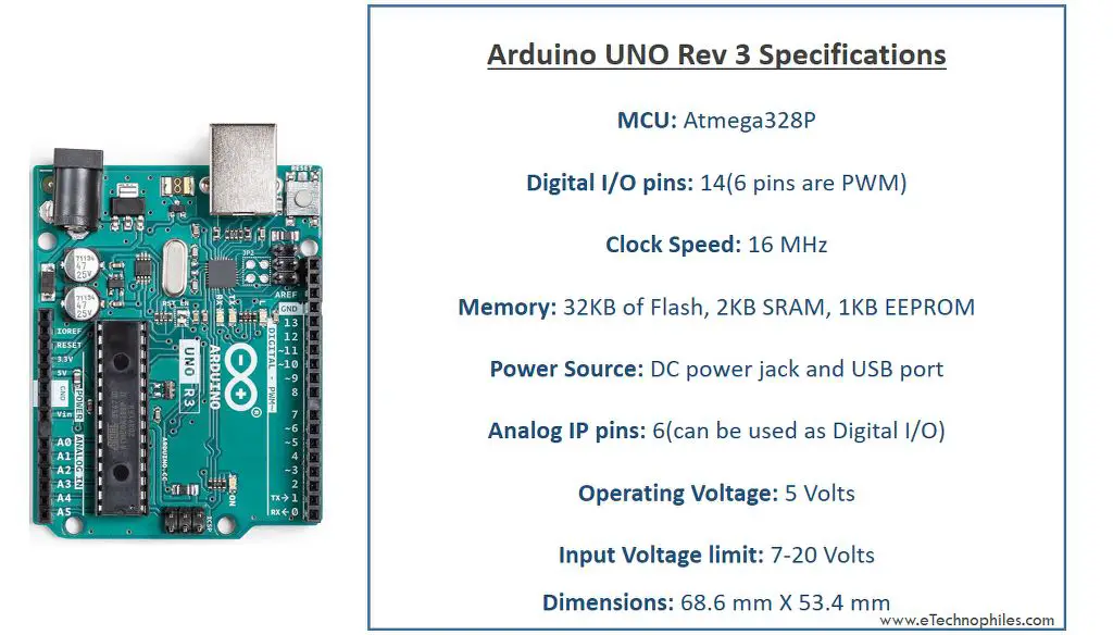
Given beneath is the brief info nigh the specs of the latest Arduino UNO Rev3 lath similar Microcontroller used, number of digital/analog pins, memory, voltage, and current ratings, etc.
| Microcontroller | ATmega328P |
| Operating Voltage | 5V |
| Input Voltage (recommended) | 7-12V |
| Input Voltage (limit) | 6-20V |
| Digital I/O Pins | 14 (of which 6 provide PWM output) |
| PWM Pins | 6( Pin three, five, 6, 9, 10, and xi) |
| Analog Input Pins | half dozen |
| Communication protocol | UART x 1, SPI x one, I2C x i |
| DC Current per I/O Pivot | twenty mA |
| DC Current for 3.3V Pin | fifty mA |
| ICSP Header | 2 |
| Flash Retentiveness | 32 KB (ATmega328P) of which 0.v KB used past the bootloader |
| SRAM | two KB (ATmega328P) |
| EEPROM | 1 KB (ATmega328P) |
| Clock Speed | 16 MHz |
| LED_BUILTIN | thirteen |
| Power Sources | Power Jack, USB port, Vin pin |
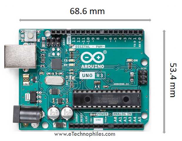
| Length | 68.6 mm |
| Width | 53.four mm |
| Weight | 25 k |
Is Arduino a Microcontroller or Microprocessor?
Arduino UNO is neither a microprocessor nor a microcontroller. It is actually a evolution board that uses a microcontroller chosen Atmega328p to perform diverse functions. You tin can say, atmega328p is the brain of the Arduino UNO development board.
Microprocessor VS Microcontroller VS Evolution board
Microprocessor: It is the encephalon of any embedded system. It performs all the numeric and logic calculations. And is responsible for executing the commands that are given to the system (like Arduino UNO). But it's important to note that a microprocessor cannot execute commands by itself. It needs external components and devices like RAM, ROM, Registers, I/O, etc, to send or store the data.
Microcontroller: A microcontroller is made up of a Microprocessor and other units required to perform sure functions like Retention units, Inputs/Outputs, ADCs, etc. That's why a Microcontroller tin can execute commands by itself. But it'due south not easy to program a Microcontroller straight due to the absenteeism of a USB port, GPIO header, etc., and hence information technology is not recommended to beginners.
Development board: A evolution lath makes it piece of cake to connect the external peripherals to the Microcontroller. It is piece of cake to program and create projects using a evolution board like the Arduino UNO.
How many programs can Arduino UNO run?
Arduino UNO is a simple microcontroller board without any operating system or powerful processor. Unlike your laptop or mobile phone, it tin run only 1 programme at a time. Of course, y'all can add together multiple tasks in a unmarried program but they volition be executed one past one.
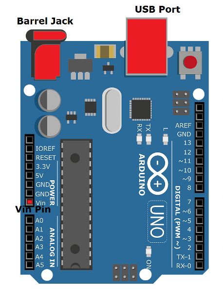
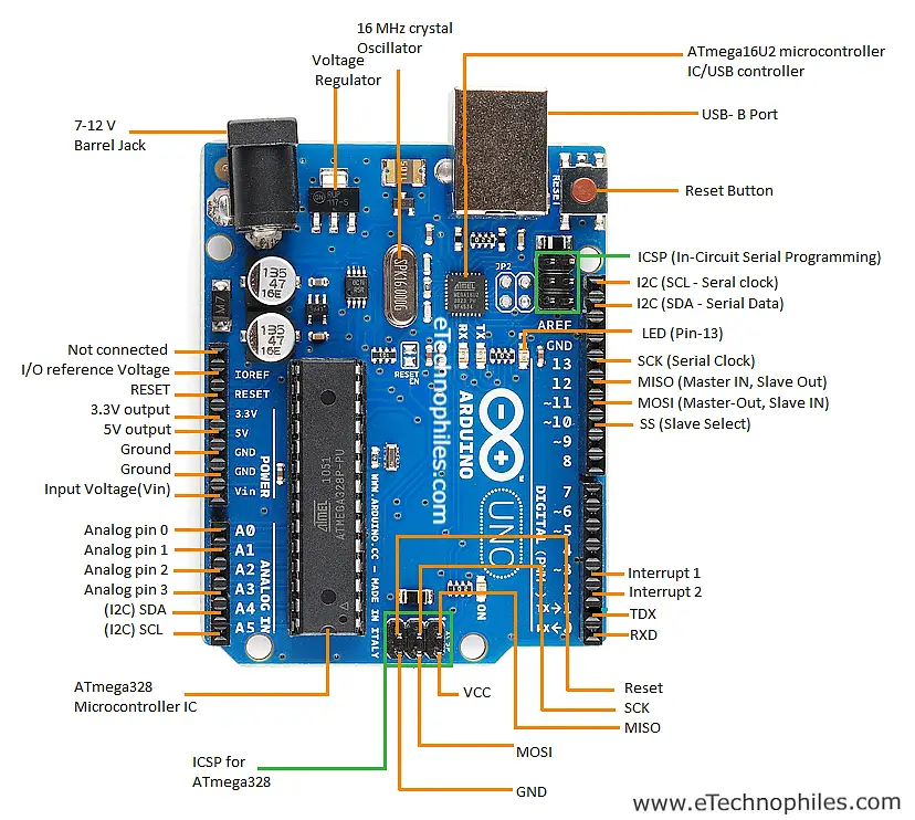
Arduino UNO Board Layout
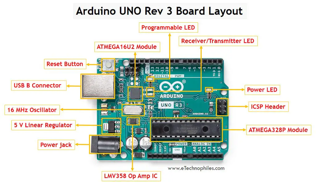
Atmega328P Microcontroller– The ATmega328p is a single-chip, high-performance, efficient microcontroller created by Atmel in the megaAVR family. It is an 8-bit AVR RISC-based microcontroller bit. It consists of32 KB Internet access provider flash memory with read-while-write capabilities, 2 KB SRAM(Static RAM),1 KB of EEPROM,23 full general-purpose I/O pins.
Atmega 16U2 Microcontroller– The Atmega 16U2 is used as a USB to serial converter in Arduino UNO.
Voltage Regulator -The voltage regulator converts the input voltage to 5V. The chief use of a voltage regulator is to control the voltage level in the Arduino lath. Fifty-fifty if in that location are any fluctuations in the input supply voltage of the regulator, the output voltage remains abiding and near v volts.
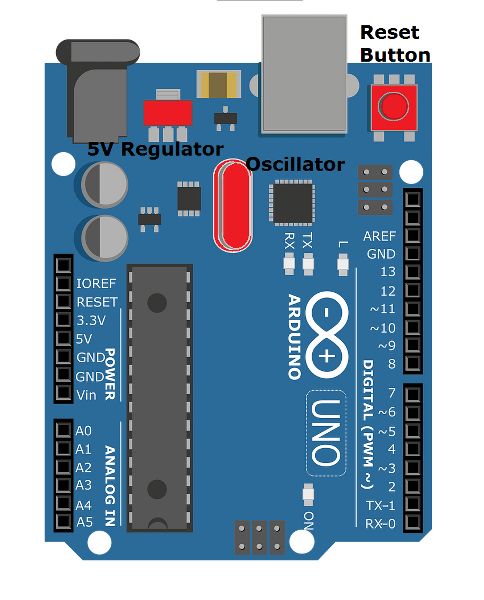
Crystal Oscillator– The Crystal oscillator has a frequency of 16MHz, which provides the clock signal to the microcontroller. It provides the basic timing and control to the board.
RESET Push–It is used to reset the board. It'southward recommended to printing this push button every time nosotros wink the lawmaking to the lath.
Barrel Jack – The Butt jack or DC Power Jack is used to power the Arduino lath using an external power supply. The barrel jack is ordinarily connected to an adapter. The board can exist powered by an adapter that ranges between 5-xx volts but the manufacturer recommends keeping it between 7-12 volts.
Note: Above 12 volts, the board may overheat and below seven volts, the voltage might not be sufficient to power the board.
USB B-port–The USB Interface is used to plug in the USB cable. This port tin can be used to power the device from the 5V supply. It allows usa to connect the board to the estimator. The programme is uploaded to the board serially from the estimator through the USB cable.
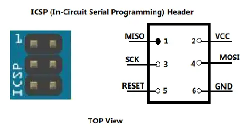
ICSP header – It stands for In-Circuit Serial Programming. We can employ these pins to program the Arduino board's firmware. The firmware changes with the new functionalities are sent to the microcontroller with the assistance of the ICSP header.
The ICSP header consists of six pins.
Arduino UNO Pinout /Pivot diagram(Updated):
How many pins are there in Arduino UNO?
If you lot take a expect at the Arduino board y'all volition notice that there are a total of 32 pins on information technology(excluding the ICSP header). Out of these 32 pins, fourteen are digital I/O pins, half-dozen are analog pins, iii GND and single 5V,3.3V, Vin and reset pin, and more than.
New Arduino UNO R3 Pinout
The picture given below is the pin diagram of Arduino UNO:
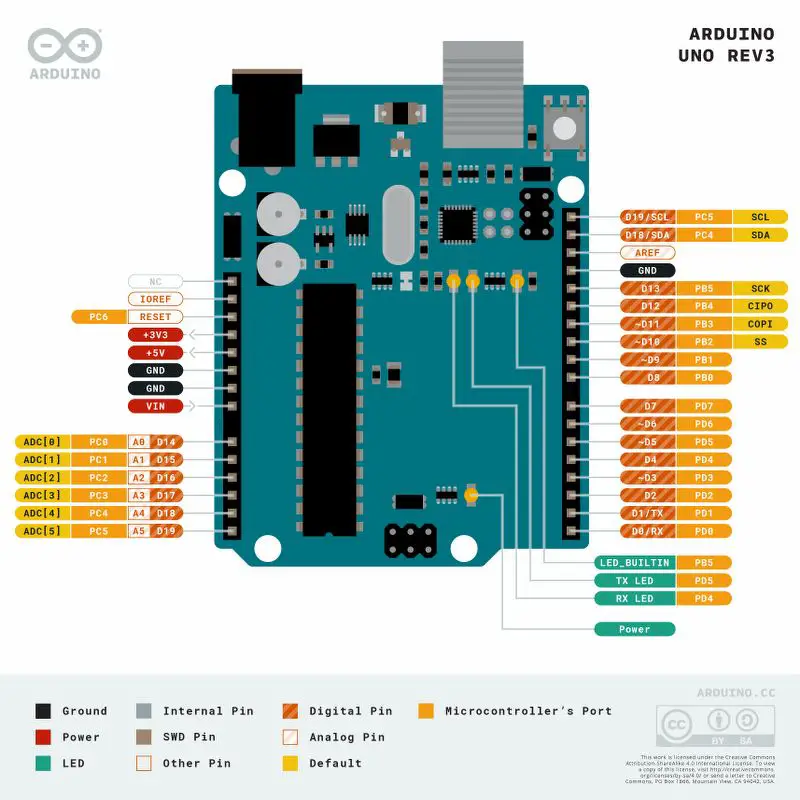
Official Arduino UNO Rev3 Pinout:
Given below is the official pin diagram of Arduino UNO Rev3 by Arduino.cc
I2C Pins on Arduino UNO pivot diagram:
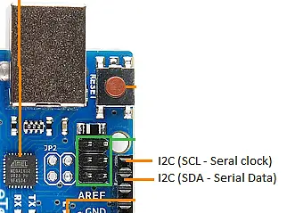
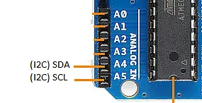
I2C is the two-wire series communication protocol. It stands for Inter-Integrated Circuits. The I2C uses two lines to transport and receive data: a serial clock pin uses (SCL) and a serial data (SDA) (SDA) pivot.
- SCL-It stands for Serial Clock. It is the pin or line that transfers the clock data. It is used to synchronize the shift of data between the two devices (main and slave). The Series Clock is generated by the master device.
- SDA-Information technology stands for Series Data. It is divers as the line used by the slave and primary to send and receive the information. That's why it is called the data line, while SCL is called a clock line.
SPI Pins on Arduino UNO pin diagram:
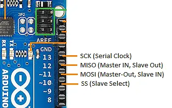
SPI stands for Serial Peripheral Interface. It is used by microcontrollers to communicate with one or more peripheral devices rapidly.
- SCK-It stands for Serial Clock. These are the clock pulses, that is used to synchronize the transfer of information.
- MISO-It stands for Chief Input/ Slave Output. This data line in the MISO pin is used to receive the data from the Slave.
- MOSI-It stands for Master Output/ Slave Input. This line is used for sending data to the peripherals.
- SS-It stands for Slave Select. This line is used past the main. Information technology acts equally the enable line. When a device'due south Slave Select pin value is LOW, information technology can communicate with the master. When it's value HIGH, it ignores the master. This allows us to have multiple SPI peripheral devices sharing the same MISO, MOSI, and CLK lines.
External Interrupts (ii and 3)- These pins can be used to trigger an interrupt on a low value, a rising or falling edge, or a change in value.
TXD and RXD-TXD and RXD pins are used for serial communication. The TXD is used to transmit the data, and RXD is used to receive the data. It also represents the successful catamenia of information.
ICSP pins:
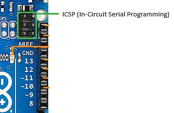
It stands for In-Excursion Serial Programming. We can utilize these pins to program the Arduino board's firmware. The firmware changes with the new functionalities are sent to the microcontroller with the help of the ICSP header.
The ICSP header consists of six pins.
Arduino Uno Pinout – Analog Pins:
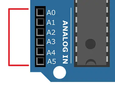
The Arduino Uno consists of 6 analog pins , which use ADC (Analog to Digital converter). These pins can serve as analog inputs but can also part as digital inputs or digital outputs. These pins have inputs in the class of Analog signals and return values that range between 0 and 1023 (because the Arduino Uno has a 10-bit Analog to Digital converter or 2ten resolution ).
An Analog to digital converter works in three stages: sampling, quantization, and digitization. Because the Arduino operates on a 0–5 volts range, the step size of the device is 5/1023=0.00488volts or 4.88mV .
Thus, we can translate a four.88 mV input voltage to whatsoever of the analog pins as ane, 9.77 mV as 2, and so on until 5 V as 1023. Anything below iv.88 mV is considered 0 and above 4.99 V as 1023.
Digital Pins:
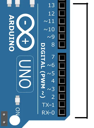
On the Arduino UNO lath, pins 0-13 are digital input/output pins.
The Arduino digital pins tin can read but ii states: when there is a voltage bespeak and when there is no signal. This kind of input is usually called digital (or binary) and these states are referred to as HIGH and Depression or one and 0.
LED (13): On the lath, there is a built-in LED connected to digital pin xiii. When this pin is HIGH or 1, the LED is switched on, when the pin is LOW or 0, it'south switched off.
PWM pins:
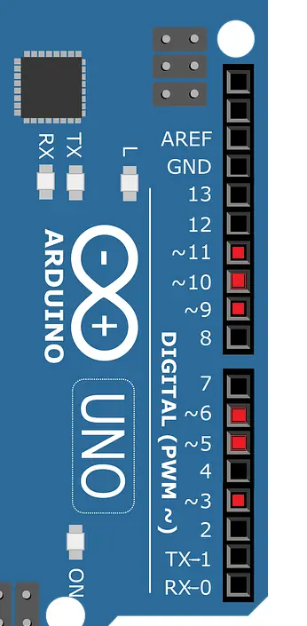
If you look closely, you will find the '~' symbol on digital pivot three,5,vi,9,x, and 11 . These pins have an additional characteristic called PWM. Hence these pins are called PWM pins.
PWM stands for "Pulse Width Modulation". It means, that an analog value is being modulated on a digital signal. Suppose you want a DC motor to run at a certain analog voltage between 0 and 5 V. This is non possible because the Arduino board is MOSFET-based.

Thus, to achieve the desired output, we can but southwardimulate an analog signal past switching our output on and off very rapidly. Thus, PWM tin can only mimic and simulate the effects of a pure analog signal, it can never perform pure digital to analog conversion (which mostly requires some active components like capacitors and inductors).
Other pins on Arduino UNO:
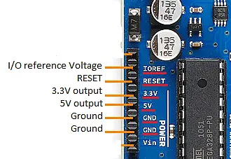
GND (Ground pins) : There are v footing pins available on the board.
RESET – Use to reset the Arduino Board. If this pin is supplied with 5 V, the lath will reset automatically
I/O Reference Voltage (IOREF) – This pin is the input/output reference. It provides the voltage reference at which the microcontroller is currently operating. Sending a signal to this pin does nothing.
three.3V and 5V: These pins provide regulated 5v and three.3v respectively to the external components connected to the board.
Vin –Information technology is the modulated DC supply voltage, which is used to regulate the IC's used in the connection. It is besides called the master voltage for IC's present on the Arduino board. The Vcc voltage value can be negative or positive to the GND pin.
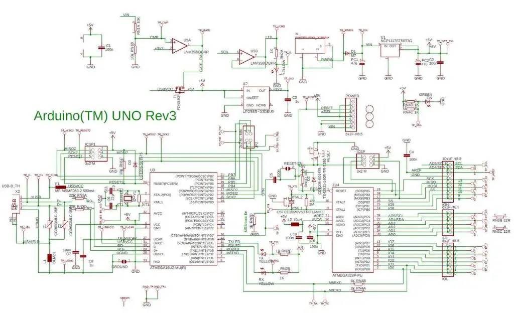
Schematic of Arduino UNO Rev3(latest):
To download the updated Schematic version of the latest Arduino UNO Rev3, click here.
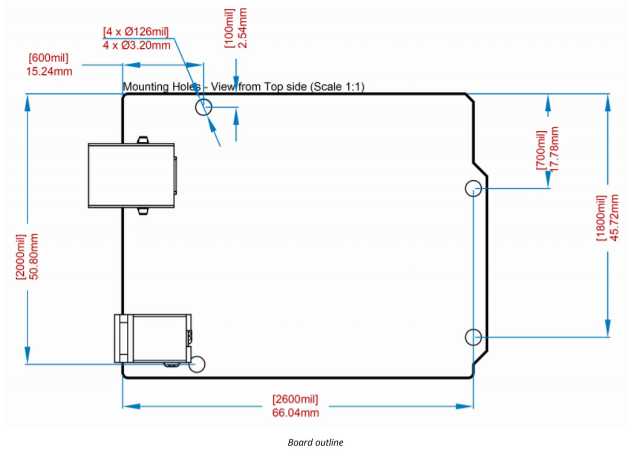
Dimensions of Arduino UNO:
Datasheet of Arduino UNO Rev3
Download the official Datasheet of Arduino UNO Rev3, from hither.
Learn More than about Arduino here:
| Arduino Projects for Beginners
| Arduino Programming for beginners

Source: https://www.etechnophiles.com/arduino-uno-pinout-pin-diagram-specifications/
Posted by: engellils1998.blogspot.com
0 Response to "How To Upload Arduino Code Into A Microchip"
Post a Comment